Systems Design
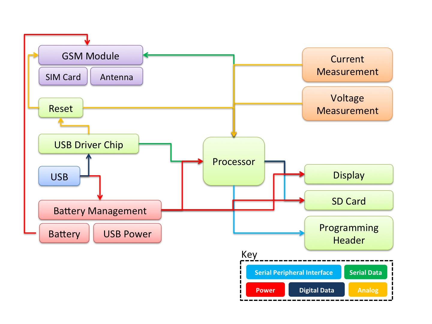
Electrical Block Diagram
Datagoo is built around the ATMEGA328P, the same processor used by many hobbyists for a variety of Arduino designs. When coupled with an FTDI FT232RL USB-Serial circuit, the board can be programmed with any computer with a USB port. Other design decisions were made in the interest of cost and simplicty. Surface mount components were chosen for ease of manufacturing. The voltage and current measurement circuits were designed to utilize the ATMEGA328P’s internal Analog-to-Digital converters, again reducing the component cost. The cell phone module was chosen for price - it is one of the cheapest GSM modules available. Also, all the components for which critical software needed to be written are avaiable in Arduino shield form, making testing custom applications more accessible.
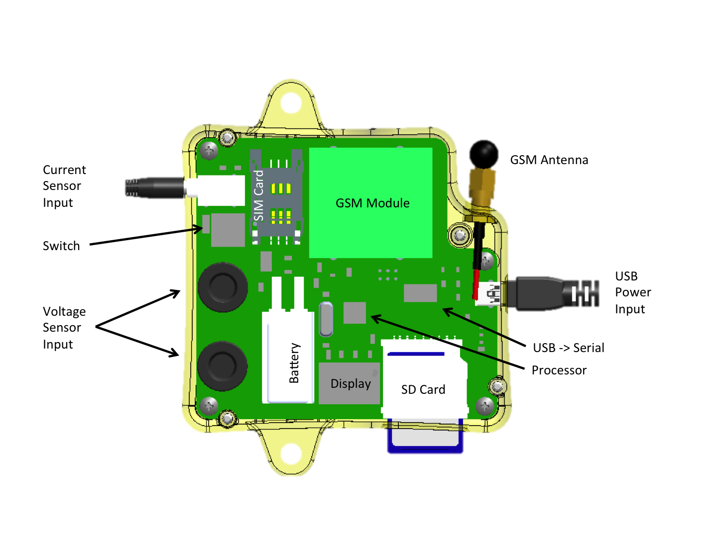
Component Locations
Voltage Measurement System
The input voltage is rectified with a bridge rectifier. Then, a voltage divider reduces the voltage by a factor of 110. Then, the now 3.3V signal is run through an op-amp buffer for measurement accuracy. Finally, the signal is fed into the ATMEGA328P’s Analog Input 1.
Current Measurement System
The Datagoo uses a “current transformer” to convert an AC signal into a readable value. A current transformer simply divides the current down. For our current transformer, a current of 100A will result in an output current of 33mA. The current is driven across a small resistor (33 ohms) to generate a voltage, which is then referenced against 1/2 * 3.3V, so both positive and negative currents can be sensed. The signal is then fed into the ATMEGA328P’s Analog Input 0.
Battery Backup System
Datagoo uses a small lithium backup battery to keep the device on in the event of a power interruption. The battery is normally charged by the USB charger, and should be nominally at 4.2V. If the USB power is disconnected, the device switches to battery power and should last for ~30 minutes.
Display System
The display is a two digit, seven segment display that is used to show the amount of kilo-Watts currently being measured by the device. The display is multiplexed - only one segment is on at a time, hence the faint flicker.
SMS Cell System
A SM5100b GSM module is used to add cell network functionality to the Datagoo. Using the account information from a SIM card, it will send status text messages to the number written down in the configuration file. Since GSM network settings are specific to the country, make sure to change the right settings in the configuration file.
SD Card System
The Datagoo is capable of reading and writing files to a SD card. This is used to log the amount of power generated as well as any faults. The user must edit a configuration file in order to use the unit.